Bundled flows are a type of high-level mapping tool for the Interface layer.
Bundled flows allow you to represent, at a high level on the Interface layer, the material flows between processes in your model. Like the process frame and bundled connector, the bundled flow allows you to use a "top-down" approach when building and navigating in models.
If the Link High-Level Map to Model check box is selected in the Interface Preferences dialog box, model users can navigate from a bundled flow to any of the flows on the Map and Model layers represented by the bundled flow.
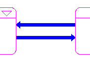
When you place bundled flows between two process frames, they look like this:
The following sections describe how to work with bundled flows by
If the Link High-Level Map to Model check box is selected in the Interface Preferences dialog box, a bundled flow is automatically created on the Interface layer when you draw a flow between two sector frames on the Map or Model layer (and vice versa).
Use the following procedure to manually place a bundled connector on the Interface layer.
Note: When the Link High-Level Map to Model check box is selected, the software enforces a one-to-one correspondence between sector-to-sector flows and process-to-process bundled flows . This means that you can have only two bundled flows between each pair of process frames: one for each direction (for example, one bundled flow from "Process Frame A" to "Process Frame B", and one bundled flow from "Process Frame B" to "Process Frame A".)
 tool.
tool.While you click and drag to place the bundled flow, press the SHIFT key and move the mouse pointer in the direction of the bend each time you want to insert a bend. Each time you press the SHIFT key while you continue to click and drag, a 90-degree bend will be put in the flow pipe.
Click and drag the square handle on either end of the bundled flow.
The movement is constrained by the boundaries of the process frames to which the bundled flow is attached.
On the Interface layer, double-click the bundled flow.
The Process Flows dialog box opens.
Polarity is used to visually indicate the cause-and-effect relationship between two model entities.
For bundled flows, the polarity is determined by the bundled flow's association to the attached process frames: an inflow always has a positive (+/s) influence on a process frame and an outflow always has a negative (-/o) influence on process frame.
Use the following procedure to display the bundled flow's polarity on the model diagram:
For more information about polarity, see Assigning polarity to building blocks.
 See Also