| Symbol |
Description
|

|
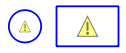
Non-negative Stock. A stock that can't go negative (the outflows will be constrained to prevent this from happening). See also non-passthru below. |

|
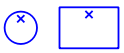
Stock. The  in the lower right hand corner indicates that a stock can go negative (this mark only appears in Model in the lower right hand corner indicates that a stock can go negative (this mark only appears in Model  . mode not in Map . mode not in Map  mode). To set this right click on the stock or uncheck non-negative in the Properties panel. Checking non-negative removes the mark. mode). To set this right click on the stock or uncheck non-negative in the Properties panel. Checking non-negative removes the mark. |

|
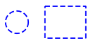
Conveyor. A stock that hold material for a set amount of time before it flows out. There can also be leakages. |

|
Queue. A stock that keeps incoming material in order and then dispatches it to downstream stocks based on their ability to take new material. |

|
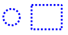
Non pass-thru Queue. As above, but outflows are computed with the assumption that inflows are 0 (see also non-pass-thru  below). below). |

|
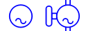
Oven. A stock that takes material, then holds it for a time, blocking new material from coming in, before releasing it. |

|
Cloud. A source or sink for content moving through a flow. The cloud is essentially a stock that is outside the boundary of the model and therefore not computed.
|

|
Converter. A variable that is used to hold intermediate computations. |

|
Delay Converter. A converter that delays the inputs and therefore has many characteristics of a stock. There are a variety of delaying builtins, but SMTH1 and DELAY are the most common. |

|
Summing Converter. A converter that adds its inputs without the needs to connectors coming into the converter. This is a diagrammatic convenience to help prevent clutter. |

|
Pathway Score. A converter reports the (raw) pathway score as computed for Loops that Matter. |

|
Loop Score. A converter reports the (normalized) loop score as computed for Loops that Matter. Computed values are available only after a simulation completes and can not be used in other variables. |
|
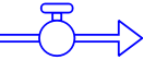
Flow. A flow, between two stocks, from a cloud to a stock, or from a stock to a cloud. Material can only flow in the direction of the arrow. If the computation of the flow value is negative the flow will be 0. |
|
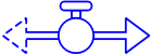
Biflow. A flow that moves material in the direction of the solid arrow, but that can also take on negative values effectively taking away material from the downstream stock. The dashed arrowhead indicates that material will be taken away, when the flow value is positive. |

|
Leakage.  Indicates the flow represents leakage from a conveyor. The second and additional outflows from a conveyor are automatically marked as leakages. Indicates the flow represents leakage from a conveyor. The second and additional outflows from a conveyor are automatically marked as leakages. |

|
Unit Converting Flow. This changes the units of measure, between the upstream and downstream stocks. For example, you could have an outflow in kilograms adding to a stock measured in grams. |

|
Connector. An indication that the starting variable (on the left in this case) is used when computing the ending variable. Connector can only go into flows, converters, and modules. |
|
Information Connector. An annotation convention to indicate that the connector conveys information (as opposed to action and consequence). The visual distinction does not affect computation. |
|
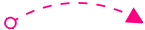
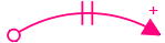
Connector with delay and polarity. Connectors can be annotated to indicate which direction the end variable change in response to an increase in the start variable and whether the response is delayed. The visual distinction does not affect computation. |

|
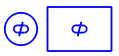
Module. A module contains a submodel. You can connect modules (using connectors) to indicate that variables in one are used in another.
|
|
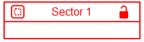
Sector. A sector is a convenience container to allow grouping of variables. It can be locked (click on the padlock) to keep everything inside of it together if it is moved. |

|
Placeholder. A Placeholder contains a list of possible variables. They can be used in tables and graphs on the model and interface and allow simple switching between variables without requiring multiple graphs. |

|
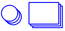
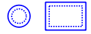
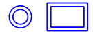
Graph. When you minimize a graph by clicking on the  button an icon for it will be displayed. Double click on the icon to restore the graph. button an icon for it will be displayed. Double click on the icon to restore the graph. |

|
Table. When you minimize a table by clicking on the button an icon for it will be displayed. Double click on the icon to restore the table. |