Causal loop diagrams are different from regular model diagrams because they depict circular connections without any stocks being displayed. This is because, in a CLD, stocks aren't distinguished from other elements; everything is simply represented by its name. To create causal loop diagrams in Stella, use the New CLD command on the File Menu. This will open the The CLD Window. Then use the variable ![]() tool to add names and the connector (
tool to add names and the connector (![]() ) tool to connect them up.
) tool to connect them up.
It is also possible to create CLDs in regular models using either modules or delay convertors. This can be useful if you want to create something that has more variety than a regular CLD, or that combines some stock and flow information into a CLD (hybrid diagrams).
Open the Model Styles panel for the new model by double-clicking on the blank model and then selecting the ![]() tab.
tab.
Modules are a good way to lay out a CLD, but the default connector width between modules is 2, and you may need to adjust individual arrow widths downward to get the effect you want.
Open the Model Styles panel for the new model by double-clicking on the blank model and then selecting the ![]() tab.
tab.
Using delay converters forces you to take the extra step of changing some of the converters to delay converters. That step can help identify links along which there must be a delay, which may make annotating your diagram easier. Connecters will have the default width of 1 when placed.
You can mix converters and modules in laying out a diagram. You can also leave modules with their shape and use these to denote the stock-like entries in the causal loop diagram. For example:
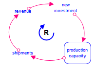
Otherwise, the methodology is the same.