Imagine you are building a business model for an airline. The causal loop diagram for the model (the “dynamic hypothesis”) might look like this:

This is the top level of the model, which comprises five modules (Customers, Fleet, Reputation, Quality, and Service). The connectors between modules indicate how values flow from one module to another. For example, you can see that entity values flow in both directions between the Customers and Fleet modules; however, entity values flow only in one direction from the Quality to Reputation modules, and from the Reputation to Customers modules. Similarly, the connectors show you that there is no direct connection between the Service and Customers modules.
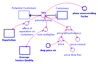
You develop each underlying module as a separate model. For example, this is what the “Customers” (customer acquisition) module might look like:

Note that this module depends on several inputs from elsewhere in the model and will not be able to run until those inputs are assigned. The unassigned module inputs are indicated visually by a double-thick border for their entity icons and a bold font for their labels:
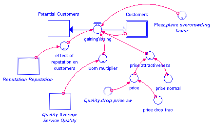
When these module inputs are assigned to entities elsewhere in the model, the module is fully defined and able to simulate as it stands in isolation.

Notice that the previously unassigned module inputs are now named this way:
The part of the name before the period indicates the module where the entity is defined (for example, “Fleet”, “Reputation”, and “Quality”). The part of the name after the period indicates the entity’s actual name, as defined in the module where the entity is defined (for example, “plane overcrowding factor” and “Average Service Quality”). Notice that the assigned module inputs are now indicated visually by an italic font for the entity’s label, and a double-thick gray border for the entity’s icon.
This module also contains an entity that is defined as a module output (remember that the Customers module had connectors indicating that it had inputs and outputs to both the Fleet and Quality modules). In the Customers module, the “Customers” entity is defined as an output. Outputs are indicated visually by a double-line border (which looks like an O in converters and flows). The name for outputs appears in a regular font.
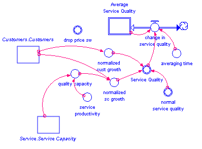
Now, let’s look at the Quality module, which tracks service quality. This is the way the module looks after the module inputs have been assigned:

In this module, there are two module inputs (“Customers.Customers” and “Service.Service Capacity”) and four module outputs ("drop price sw", “Average Service Quality”, "Service Quality", and “normal service quality”).
A module input can be assigned to
If you look back at the top-level of the module, you'll see that the Customers and Service modules are both connected to the Quality module via incoming connectors, so module outputs from both of those modules are available to be assigned as inputs to the Quality module.