Connectors
A connector is a type of building block used to connect model variables to each other. Connectors indicate an immediate effect of one variable on another variable. Since stocks change only over time, this means that connectors can only end on converters and flows. Connectors can start from stocks. Connectors can also start from and end in Modules (see Working with Modules).
There are two types of connectors that are distinguished by their visual appearance.
- Action connectors transmit the action resulting from a decision. An action connector is represented by a solid, directed wire.
- Information connectors carry information that's used to arrive at decisions. An information connector is represented by a dashed wire.
For example, an information connector may carry information about milk prices to consumers. Consumers decide what to buy, and then take action (represented by an action connector) to purchase a certain quantity of milk that day/week/month.
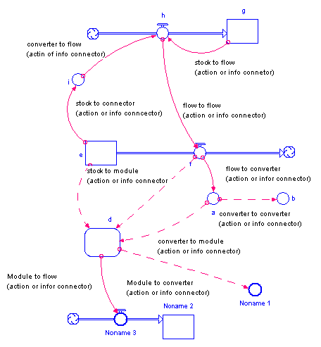
The following picture illustrates how connectors can be used in a model.

Note: The software won't allow either type of connector to send input directly to a stock. The only way to change the magnitude of a stock is through a flow.
To place a connector on the diagram
- Click the connector
 tool.
tool.
- By default, the action connector is selected. To place an information connector in your model, choose Info Connector (
 ) from the connector tool's dropdown menu.
- Click the location on the diagram where you want the connector to start. The starting place must be within the boundary of a stock, flow, converter, or Sectors.
-
Drag to the flow, converter, or module where you want the connector to end.
Note: If you draw a connector that creates a chain of converters and/or flows that ends where it started, a message tells you that you would be creating a circular connection, and the connection isn't created.
- Release the mouse button to place the connector.
For more information about placing objects on the diagram, see Working with Building Blocks.
Creating Bezier connectors
- Click the connector
 tool.
tool.
- Click the location on the diagram where you want the connector to start. The starting place must be within the boundary of a stock, flow, converter, or Sectors.
- Drag the mouse and press the Shift key at each point you want to drop an anchor for the Bezier curve.
-
Drag to the flow, converter, or module where you want the connector to end.
- Release the mouse button to place the connector.
To reposition or reshape a connector
- Select the connector's start handle (the opposite of the arrow end) and drag it along the perimeter of the variable to which it's attached.
- For Bezier connecters: drag any of the shape points.
- To add points to a Bezier connector: grab the arrowhead, drag it away from the object it's connected to, and use the Shift key to drop additional anchor points.
- To drop points from a Bezier connector: delete the connector and redraw it.
To choose polarity for a connector
Polarity is used to visually indicate the cause-and-effect relationship between two model variables.
For connectors, you can choose the polarity you want to assign (positive or negative), based on the interaction between the two variables.
- Right-click the connector's start handle, choose Polarity from the menu that appears, and then choose +/s, -/o, or None.
For more information about polarity, see Assigning Polarity to Connectors.
To delete a connector
- Select the connector's start handle, and then choose Delete from the Edit menu (or right-click, and then choose Delete; or press the DELETE key),
- or Drag the arrow head away from the connection point and let it go. You can also use this technique to move a connector to a different end location.
 See Also

